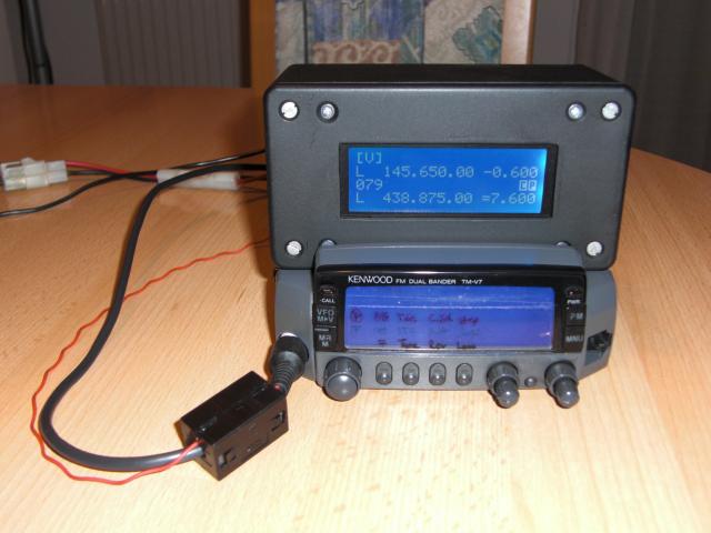
External Display for Kenwood TM-V7
The "Blue Wonder" from Kenwood suffers from a general problem: The display will fail almost for sure after some time of usage. Since there seems to be no more support from Kenwood, I decided to bring back my TM-V7 to life on my own with an external display.
German "Funkamateur" magazine published my article in 09/2010. Those of you that don't have access to that zine will find my manuscript right here as a PDF file, but be aware that it's rather large (1.4 MB!). Source and HEX file are available at the Funkamateur download aera for the public.
I have translated the German text to English and uploaded it as PDF, the result might not be of the same quality in language as Shakespear's work but I hope it's sufficient to understand what it's all about. :-)
Enjoy!
Please note: A few users have reported that their freshly built external display does not work and only shows "Transceiver: unknown" instead. Please double check and ensure that you have set the right fuses when programming the ATmega 8 because it runs from internal 1 MHz clock source out of the box which leads to wrong serial line speeds with this software. The controller must run from internal oscillator @ 8 MHz to set up correct communications with the transceiver.
Fuses: CKOPT = 1 ; CKSEL3..0 = 0100 ; SUT1..0 = 10 ("1" meaning an unprogrammed fuse resp. unchecked checkbox in PonyProg).
Update: It seems different batches of ATmega8 controllers have a quite wide variation on internal clock accuracy. At least OM Philippe, F1IQE had troubles getting to work the communication between the TM-V7 and the display, most likely due to inaccuratly generated baud rates using the internal clock. The display finally could be brought up using an 8 MHz XTAL and two 22 pF caps on pin 9 and 10 (XTAL1 and XTAL2). The fuses must be set to external XTAL clock source in this case:
Fuses: CKOPT = 1 ; CKSEL3..0 = 1111 ; SUT1..0 = 11 (meaning all unprogrammed resp. unchecked in PonyProg).
If you use a cheap programmer providing no external clock to the ATmega8 being programmed you might not be able to read/program the device anymore after changing the fuses to external XTAL clock source. In this case I'd recommend modifying your programmer with an external XTAL (4..8 MHz will do) and two 22 pF caps, enabling you to program devices with either clock sources.
Warning! Do NOT change/activate the RSTDISBL fuse on your ATmega8, this will change the RESET pin into a normal I/O pin and disables the RESET function. Without RESET input the ATmega8 can NOT be programmed again by (simple) serial programming, you will need an improved programmer to fix this, or a second ATmega8 programmed with a special software loaded to re-activate the RESET pin on your modified chip.
Here you'll get a quick look at the finished unit (click image to enlarge):

These people have reported that they are planning to build or have already successfully built their own display:
- Javier, EB1WB - success! :-)
- Barry, K5VIP/KG4BP - success! :-) (reported via PD2RLD)
- Heinz, DL7HKL & Franz, DG7CAH - success! :-)
- Arnold, PA1AK - success! :-)
- Imre, HA0BW - success! :-)
- Matthias, DH2LAB - success! :-)
- Udo, DK1FUN - success! :-)
- Jean-Pierre, F1GBJ - success! :-)
- Philippe, F1IQE - success! :-)
- John, SV2CPH - success! :-)
- Giancarlo, SV0XBR - success! :-)
- Roland, PD2RLD - success! :-)
- Robi, S52DK - success! :-)
- Zolika from ??? (callsign unknown) - success! :-)
- Branko, S56WLB and Bob, S59RK - success! :-)
- Harvey, WB5MCT, Victoria/TX, USA
- Michael from Germany (callsign unknown)
- Jeff from Washington/MO, USA (callsign unknown)
Roland, PD2RLD runs a nice Dutch web site with lots of HAM stuff and has now set up a comprehensive page in English language with lots of hints for building the display and programming the controller. Thanks to Roland for all the work and the cooperation! :-)


